Circular Polarizers and Orthomode Transducers
OMT's and associated linear to circular polarizers find uses in a wide range of instrumentation including radiometers and multipolarization radars.
Waveguide OMT's are common in the Microwave region but are rare to find in the MM-region, given their manufacturing difficulty.
Signals entering the circular input of an Orthomode transducers are separated into vertical and horizontal components at the two rectangular waveguide output ports. A circular polarizer can be placed ahead of the circular OMT input to convert incoming CW and CCW circular polarized (CP) radiation into two linear outputs: The CP is first transformed into linear polarization before being routed by an OMT to its two rectangular output ports.

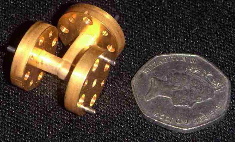
The photo shows an 94 GHz waveguide OMT designed by MAAS and built by Thomas Keating. Very high precision machining process are required to achieve the tolerances required. (Tolerances of +/- 4 microns are needed in parts of the structure).
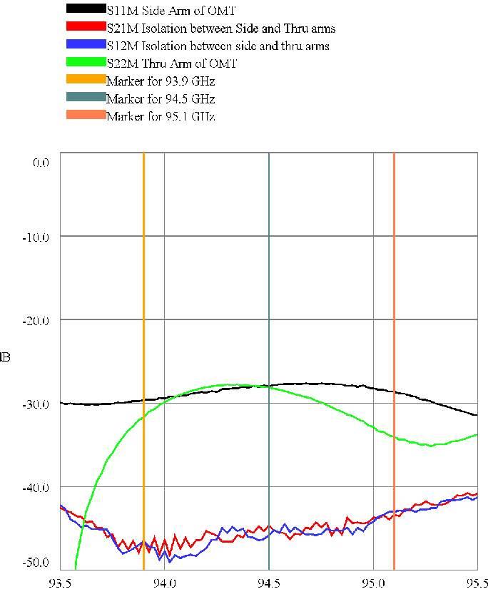
The VNA measurements - on an OMT plus polariser plus corrugated horn - illustrated below show isolation between the two output ports of more than 40dB and Return losses of better than -25dB. The frequency range is 93.5 to 95.5 GHz. The OMT will work over wider band than this, but as the bandwidth is increased, performance may suffer a little.
